Flyback Transformer Design Step By Step

Step By Step For An Optimised Flyback Design
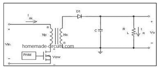
How To Design A Flyback Converter Comprehensive Tutorial Homemade Circuit Projects
Designing Isolated Flyback Converter Circuits Transformer Design Calculating Numerical Values Basic Knowledge Rohm Tech Web Technical Information Site Of Power Supply Design

Step By Step For An Optimized Flyback Supply Design Pt 1 Of 2 Ee Times

Designing Isolated Flyback Converter Circuits Transformer Design Structural Design 2 Basic Knowledge Rohm Tech Web Technical Information Site Of Power Supply Design

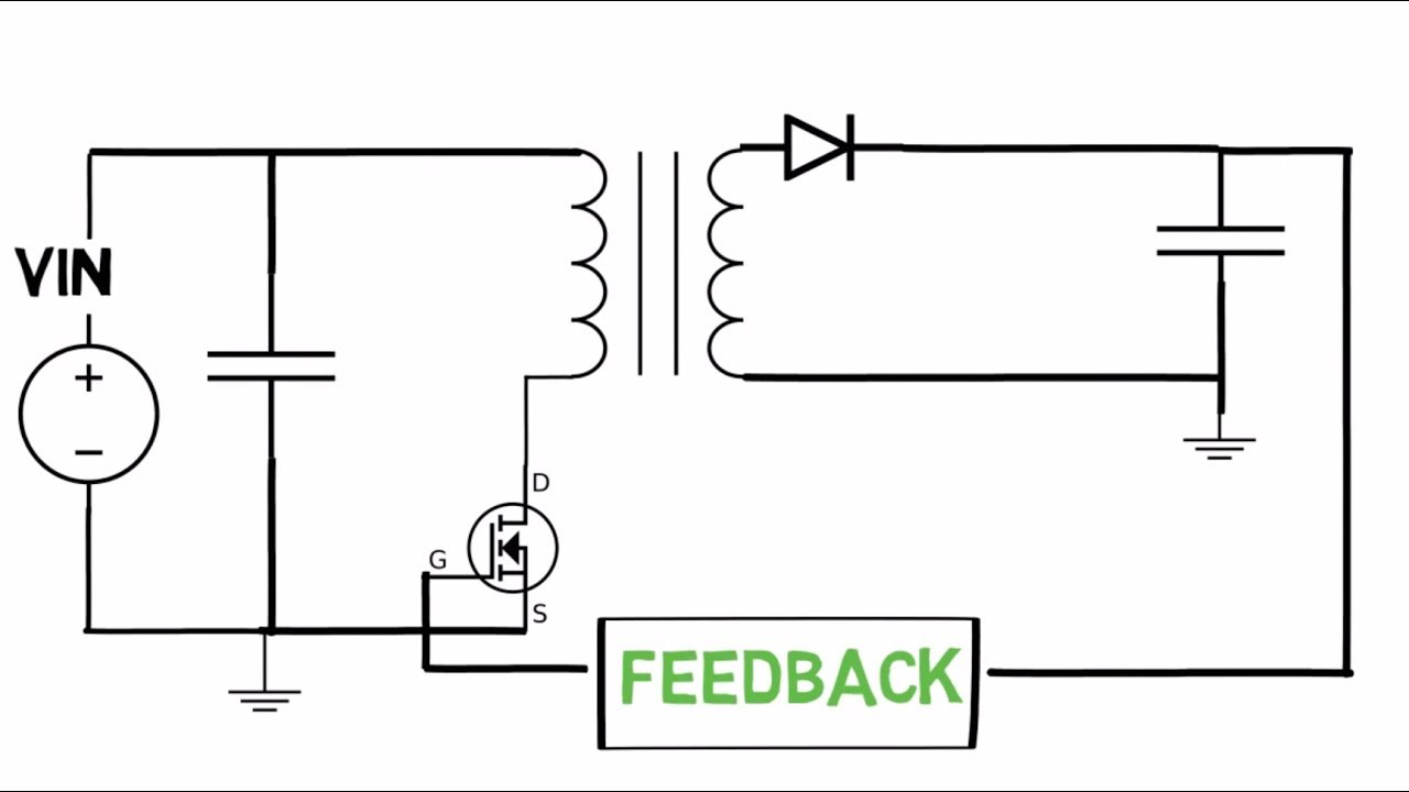
Step By Step For An Optimised Flyback Design Isolated Close Loop Design Part 2

Dcm flyback design equations and sequential decision requirements step 1.
Flyback transformer design step by step.

How Flyback Converter Works Operation And Principle Electronicsbeliever

Flyback Converter Electronicsbeliever

Isolated Flyback Converter Basics What Is Switching Ac Dc Conversion Basic Knowledge Rohm Tech Web Technical Information Site Of Power Supply Design
Flyback Converter Serves Battery Powered Ccd Applications
Flyback Converter Design Explained Part 1 Selection Of Core Youtube

Step By Step For An Optimised Flyback Design

Designing Isolated Flyback Converter Circuits Selecting Critical Components Output Rectifier And Cout Basic Knowledge Rohm Tech Web Technical Information Site Of Power Supply Design

Design Of Series Connected Forward Fly Back Step Up Dc Dc Converter Semantic Scholar

Cascode Flyback Converter Using Multilayered Coreless Pcb Step Down Download Scientific Diagram

Pdf High Efficiency Step Down Flyback Converter Using Coaxial Cable Coupled Inductor Semantic Scholar

Pdf Analysis And Design Of The Flyback Transformer

Step By Step For An Optimised Flyback Design Isolated Close Loop Design Part 2
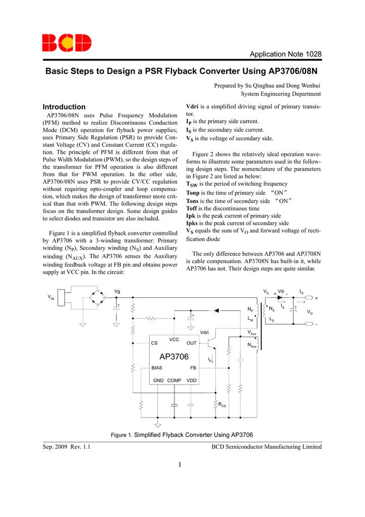
Basic Steps To Design A Psr Flyback Converter Using Ap3706 08n

An Isolated High Step Up Forward Flyback Active Clamp Converter With Output Voltage Lift Semantic Scholar

Quasi Resonant Flyback Step By Step Design Guide Electronicsbeliever

Design R C Snubber For Flyback Converter Electrical Engineering Stack Exchange

Dead Time Losses In Synchronous Rectifying Step Down Converters Basic Knowledge Rohm Tech Web Technical Information Site Of Power Supply Design

Pdf Transformer Selection Calculation For The Design Of Flyback Switching Power Supply
Https Encrypted Tbn0 Gstatic Com Images Q Tbn And9gcqci56y0lzcshdzcy88l8rx3kf7yu4t97auqhe2a97spvzca1lh Usqp Cau
Source : pinterest.com
